
This page is a detailed, step by step, instruction and tutorial set to help demystify the process behind using Maxim DL to extract photometric light curves from a series of image. This tutorial assumes that the images are not yet calibrated, but does assume that a method for image calibration is at least partially understood. The page contains both general instructions for Maxim DL photometry as well as an actual tutorial with downloadable practice images.
Calibration
The first step in performing photometry on an astronomical image is to calibrate the image. When we talk about calibrating, or reducing the image, we’re referring to: subtracting a dark frame from the image, subtracting a bias frame from the image, dividing the image by a normalized flat field image, bias subtracting the dark image, and finally bias and dark subtracting the flat field image. This may seem very complicated but fortunately Maxim handles most of the details.
Gathering Calibration Images
The most important thing you have to decide is how you want calibrate your images. In general there are only two schools of calibration techniques commonly found in practice. The distinguishing point between the two schools is whether or not to use bias images.
To Calibrate with Bias Frames:
- Bias subtract your darks.
- Bias subtract your flats.
- Dark subtract your flats.
- Bias subtract your images.
- Dark subtract your images.
- Flat your images.
To Calibrate without Bias Frames:
- Dark subtract your flats.
- Dark subtract your images.
- Flat your images.
Now I know what you’re thinking, “why do 6 steps when 3 will do?” The reason why is because calibrating with bias frames allows you to use dark frames that are not the exact exposure time as the light images you are calibrating. This allows you to scale a dark frame for a smaller exposure. For example you can dark subtract an image that was exposed for 120 seconds as well as an image that was exposed for 160 seconds with a single dark frame that is 160 seconds long. This is useful when your data’s exposure time tends to vary throughout the night. Otherwise you would have to take a series of 160s darks as well as 120s darks. For more information on auto scaling refer to Maxim’s calibration help pages.
Taking the calibration images
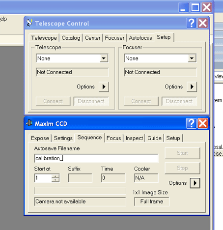
1. Connect to all required hardware in Maxim. (Camera, filter wheel, telescope)
2. Send telescope to the flat field location. (We take dome flats, and sky flats.)
![]() Don’t forget to turn off tracking!
Don’t forget to turn off tracking!
3. Enter a name for your calibration files in Auto save Filename text field. (I like “calibration”.)
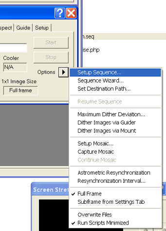
4. Click the Options arrow and select Setup Sequence… from the drop down menu.
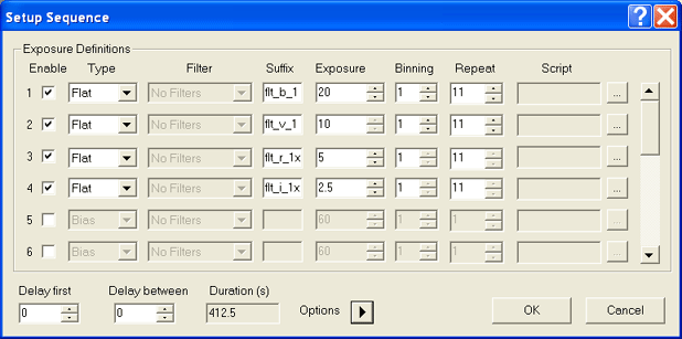
5. Setup your desired sequence to match your equipment’s requirements. Included are two example sequences for taking darks, flats, and biases. To load these sequences save them locally to your hard disk. Open the Sequence Setup… menu in Maxim and click the Options arrow and select Load Sequence… Browse for the “.seq” file you wish to load and click Open.
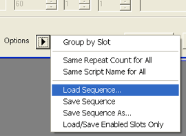
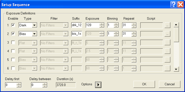
6. To take dome flats your sequence would probably look something like the one shown below. However, if you wish to take sky flats you would probably want to make sure the Group by Slot menu item listed in the Options drop down list was selected. This makes it possible to take images with the blue filter first, allowing you to get an earlier start on the evening and hopefully to obtain more flats before the sun gets too low in the sky.
If you will be taking sky flats, be sure to lower the Repeat number so that you can at least have a few flat field images before the brighter stars start poking out. If you finish up early you can always rerun the sequence.
![]() Something else to keep in mind is that it is impossible to focus your scope before the sky darkens and its equally difficult to take dusk sky flats once it gets dark. So, if you focus each night or throughout the night keep in mind that changing focus alters flats. In most cases the effect is small enough to ignore. But take the time to characterize your system before assuming that its not a big deal.
Something else to keep in mind is that it is impossible to focus your scope before the sky darkens and its equally difficult to take dusk sky flats once it gets dark. So, if you focus each night or throughout the night keep in mind that changing focus alters flats. In most cases the effect is small enough to ignore. But take the time to characterize your system before assuming that its not a big deal.
7. Take your darks. Darks take a while, and as you’ll see later, we have to get a lot of them each night. I generally begin darks and bias frames in the late afternoon. These require nothing but time, so doing them during daylight will save dark time later. You can also take darks and biases after sunset and before astronomical twilight ends (Sun more than 18 degrees below the horizon). In the summertime twilight lasts a very long time. In the winter, not so much.
![]() When setting up your dark and bias sequence remember it is best practice to get a dark for every exposure, temperature, and binning you collected data with during the night. So be sure that your camera is cooled to the temperature you will use when taking data. Also, if you don’t want to use multiple dark exposurses, then you must have a set that has an exposure at least as long as your longest-exposure science image will have. You can always scale the dark exposures down later to match that of your science images, but you cannot scale the darks up.
When setting up your dark and bias sequence remember it is best practice to get a dark for every exposure, temperature, and binning you collected data with during the night. So be sure that your camera is cooled to the temperature you will use when taking data. Also, if you don’t want to use multiple dark exposurses, then you must have a set that has an exposure at least as long as your longest-exposure science image will have. You can always scale the dark exposures down later to match that of your science images, but you cannot scale the darks up.
Setting up Maxim’s Calibration Engine
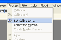
1. Under Maxim’s Process menu select Set Calibration..
This should open a window that looks like this.
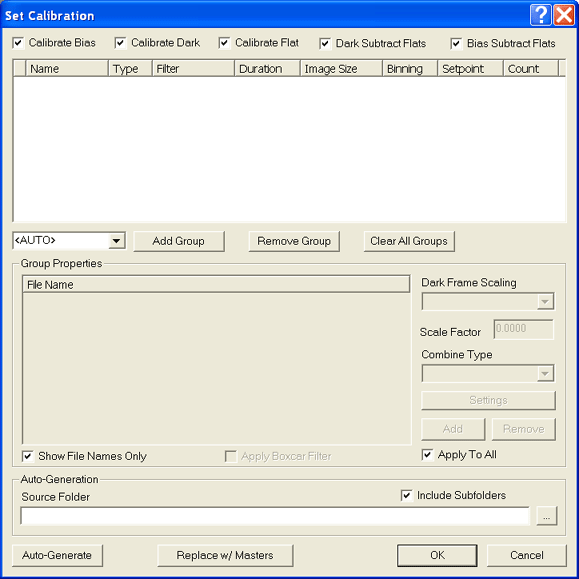
2. If you are calibrating with bias frames select all check boxes across the top of the window.

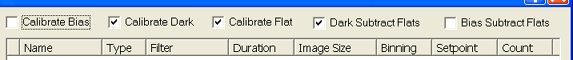
If you are not calibrating with bias frames only select the three middle check boxes.
3. Next we have to tell Maxim where our calibration files are located. To do this click the “…” button at the lower right of the Set Calibration window.
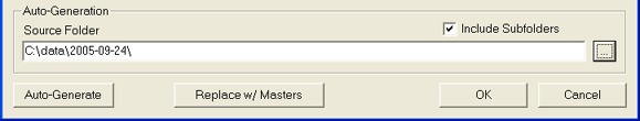
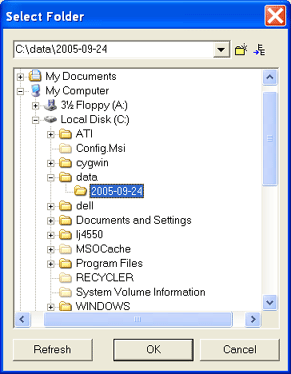
When prompted browse for the folder containing the appropriate calibration images and click OK.
4. Maxim has the ability to sort out which files are which in the calibration folder. When you return from the Select Folder window, click the Auto Generate button to have Maxim setup your calibration groups.
5. Once this is completed, Maxim should list all the different available calibration groups it found in the specified folder.
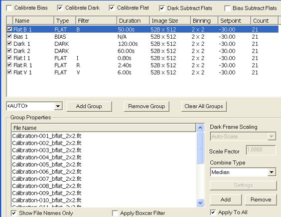
![]() Be sure to set the Combine Type to Median. This will insure that cosmic rays are properly removed from our calibration images.
Be sure to set the Combine Type to Median. This will insure that cosmic rays are properly removed from our calibration images.
Also, make sure that all the calibration files that you need are listed. Maxim will not complain if particular files are missing. It’s primary directive while calibrating images is to take the process as far as possible with the images provided.
We should now be ready to calibrate our images!
Calibrating the Images
1. Open the File menu and select Open.. Select and open all the files you wish to calibrate.
Make copies of your data before you open it so that you can use the File menu’s Save All command after your data has been calibrated.
2. Click on Calibrate from the Process menu.
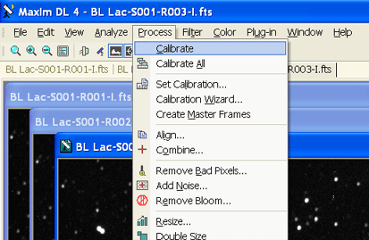
If everything goes as planned your images should now be calibrated! Take the time to look through them to make sure everything worked properly.
Preparing for Performing Photometry
Calibrated Images Download
Download a set of pre-calibrated images, in the infra-red, of the AGN BL Lac here. Unzip the .fts images to a folder on your computer and then open the files in Maxim DL. There are a total of 6 images and they have already been calibrated. Begin by using the image titled “12-BL Lac-S001-R001.fts”.
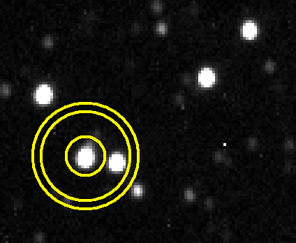
One of the most important steps in performing good photometry is determining the proper aperture, gap, and annulus sizes. The aperture is the circle in which we measure the brightness of the object. The gap is the part of the circle we use to exclude nearby objects that may be in close proximity to our object, and the annulus is the outer circle used to determine the average background light per pixel.
These three quantities are related as follows:
Star Brightness = Sum of the pixel values inside the aperture – the average background light per pixel in the annulus * the number of pixels inside the aperture
Aperture Size
There are two things to consider while choosing the appropriate aperture size. First, what is the Full Width Half Maximum (FWHM) of the brightest star in the field. Second, how much can that FWHM change from night to night.
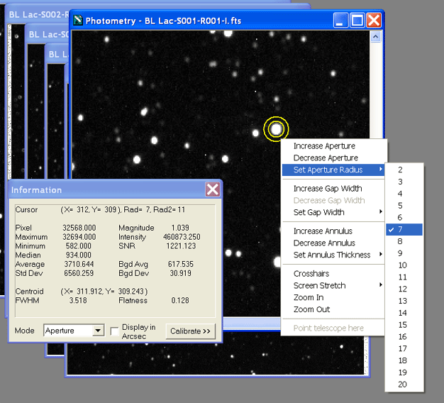
Open the Information window from the View menu. In the Information window there is a number that relates the brightness of a star with its apparent width. This is the Full Width Half Maximum. Its labeled FWHM. Below is a plot of a cross section through the center of a star. The x axis represents illustrates the width of the star in pixels and the y axis represents the brightness of the star.
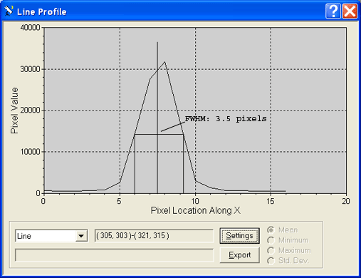
In this case, the FWHM of the star is 3.5 pixels wide. As a general rule your aperture should be set to 1-1/2 times the FWHM of the brightest object in your sequence. You can determine the brightest object in the sequence by looking in the AfH Object Catalog.
And you can determine the full FWHM of that object by opening up the Information window under the View menu and double clicking the object. If the object is visibly larger than your aperture right click anywhere in the image and under the Set Aperture Radius menu select a value visibly larger than the object your analyzing. The FWHM in pixels is list in the information window.
Sizing Your Aperture I
You can find the star field for BL Lac on the AfH Object Catalog (AfHOC) page here. Scroll down to the section titled Sequence Information.
Note: Your image may not be orientated in the same direction as the star field on the AfHOC page. To align them in the same orientation, in Maxim DL, select from the menu bar edit and then use the rotate commands to rotate your image as appropriate.
On the BL Lac webpage, find the star labeled “B” and match that star with the same star in your Maxim DL image, this is the brightest star within the immediate field. You will notice that below the field image on the website there is a table of the reference stars’ brightness for each type of filter. You will need this table later on.
Once you have located the brightest star listed on the AfHOC page in your image, double click on that star in your Maxim DL field image. The aperture gap and annulus should now appear as yellow and your cursor should now be a standard arrow cursor. Use the arrow keys on your keyboard to position the star in the center of your aperture. Note whether your aperture is smaller, larger or about the same size as the actual star and adjust your aperture so that it is slightly larger than the star (by right clicking anywhere in the image). Now find the star’s FWHM in the information window and rest the aperture size to 1.5 times the star’s FWHM value. In our trails, we found the FWHM to be 4.108.
In an idealized optical system we might expect that all the stars in our image would be no more than one pixel wide because they are so far away from us; they appear as point sources to our instruments. A point source is an object who’s shape is unresolved by our equipment. However, the stars in our images do appear to have a finite size. This is caused both by the wave nature of light and by atmospheric distortions. For ground-based telescopes it is the atmosphere that typically dominates, but even the Hubble Space Telescope must deal with finite resolving power due to the wave-properties of light. In general, the brighter a point source is, the wider it appears in our images, but all point sources will have a shape approximating a Gaussian light distribution. The relationship between a point sources’ width and height is its FWHM.
Every point source in a digital image has the same FWHM. Some of the things that effect an images’ FWHM are the size of the telescope aperture, the quality of the optics, the accuracy of the focus and the steadiness of the night sky (seeing). The first two items are for the most part constant night to night. However, the last two items vary dramatically from night to night and hour to hour.
The FWHM is important because you never want to change the aperture size used to analyze an object. Keeping the aperture size large allows you to use the same aperture size as variations in seeing conditions, etc., slightly modify the FWHM over the course of the night. So, forget the 1.5 times the FWHM and stick with 2 times the FWHM. (If possible) You’ll thank me later when you’re being awarded your Nobel prize. Of course, if your field is very crowded, then you will have to be sure to use an aperture small enough to only include one object at a time. Crowded field photometry is a specialty that is beyond this simple tutorial.
Tutorial: Sizing Your Aperture II: Reset your aperture’s size to double the brightest star’s FWHM. Record what value you get. We set the Aperture to 8 and the star’s FWHM became 4.110.
The Annulus
There is no general rule on the appropriate size of the background annulus. It’s size should be about that of the analysis aperture radius. It should have no other object prominently visible inside of it and is often limited by the proximity of nearby objects.
The Gap
The gap is used only if you have an object nearby interfering with your background annulus. Use the gap to create a buffer region between the analysis aperture and the background annulus. If you have an object that is *bleeding into your object* do not attempt to use simple aperture photometry to determine the object’s brightness. An example image of using the Gap to exclude nearby objects can be found at the AAVSO website here.
Adjusting Your Annulus & Gap: Now find BL Lac in your image and double click on it. Again, use the cursor keys to center your aperture on your object. Set your annulus (again by right clicking anywhere in the image and selecting Set Annulus Thickness) to as close to your aperture size as possible, making sure that other objects do not significantly fall within the annulus. If you have a default gap width, try setting it to zero (again by right clicking anywhere in the image and selecting Set Gap Width).
If the zero width gap and annulus size include other objects, adjust the annulus size first before attempting to “exclude ” the included object(s) with the gap width setting. Record the FWHM for BL Lac. With a gap of 0, annulus of 7, and aperture of 8; we found BL Lac’s FWHM to be 4.185.
Performing Photometry with Calibrated Data
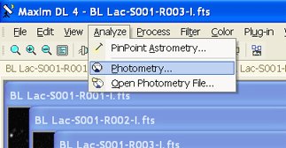
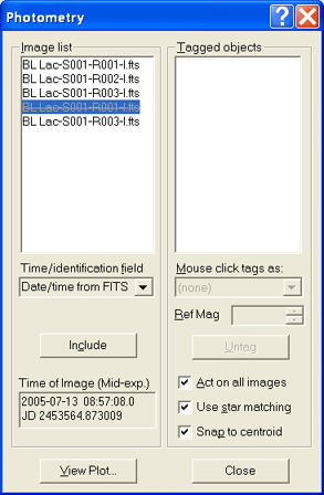
1. Select the Photometry… menu item under the Analyze menu.
2. Under the Image List select each file and visually inspect it for problems that might prevent you from wanting to perform photometry on it. For example look for images that are grossly out of focus. If there is an image that you want to exclude, click on that image in the Image List window and select the “Exclude” button. Exclude any files that you don’t wish to perform photometry on. Also, make sure you aperture settings work with each image. If they do not consider excluding that image or changing your aperture size.
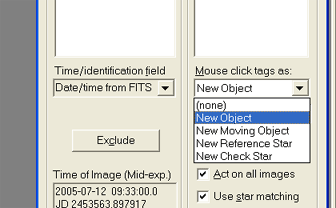
3. On the Mouse click tags as drop down menu select New Object. (You may have to select a non-excluded file to enable the drop down menu.)
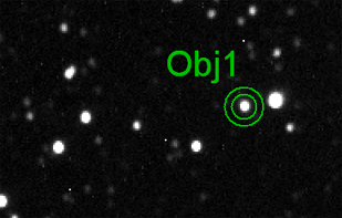
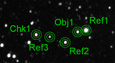
4. Click on the center of the variable object who brightness you want to determine (in this case BL Lac, which is centered between the two lines in the AfHOC’s BL Lac Sequence Information image). The object will be tagged like the image below.
5. Select New Reference Star from the Mouse click tags as menu.
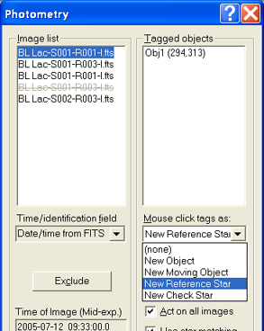
6. In your image, tag, one-by-one, the sequence stars listed in the AfH object catalog. Each time you add a reference object indicate its know magnitude the in Photometry window. Use the table below the AfHOC BL Lac Sequence Information image. Use the the magnitudes in the “I” column, as your tutorial images have all been taken with the I filter. If you have four or more sequence objects add all but one of them as reference objects. Save the last as a check star. Otherwise add all the stars as a reference objects.
7. Select New Check Star from the Mouse click tags drop down menu. If possible add the last sequence object as a check star. Choose the sequence object who’s known magnitude is closest to the unknown variable object. When you’re done your image should look very much like this.
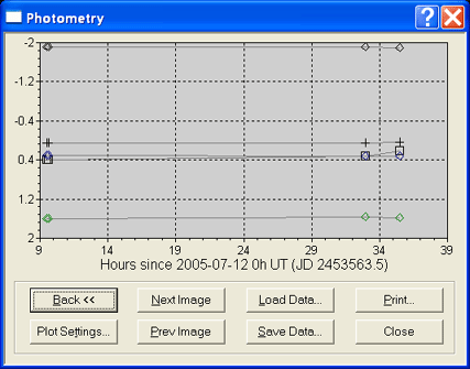
8. At this point we’re ready to hand the work off to Maxim. Click the View Plot button. This will show you a light curve of the selected objects.
9. Photometry in Action: After finishing step 8, use the Next Image and Prev Image buttons to cycle through the images. Make sure that all of the object, reference, and check star markers in the images are on the same objects. Sometimes the aperture will have moved off of a star, in which case you can simply click and drag the aperture back over the correct star (wait for the cursor to change to a small hand before you click and drag).
10. If you are satisfied with your results, click the Save Data. button to save the light curve data to disk as a comma separated Excel file. Click the back button and write down which reference stars belong to which object in the image. This will help you make sense of your light curve data.
Once you are finished, you can create a plot from the excel file (which will look very similar to the initial plot from Maxim DL). You can download our Excel file of the data here.